
Introduction
The LEDWiz is a hardware device by www.GroovyGameGear.com that controls LED's. Using the LEDWiz is the latest way to bling out your CP for your arcade machine. You can read more about it's specs here. Make sure you read the official LEDWiz Instruction Sheet before attempting anything.
A LEDWiz has 32 outputs available for lighting LED's. Each Output has 49 levels of brightness using PWM. You can use the LEDWiz in two ways; to control SINGLE LED's or RGB LED's. Single LED's take one output for one LED, and the RGB LED's take 3 outputs one for Red, Green and Blue.
My interest in the LEDWiz started after writing a plugin to support it for the GameEx front end. The more features I added to my plugin the more I realised I wanted to add this feature to my cab. What really sold me on the idea was the fact I could just replace the buttons on my CP and wire up the LEDWiz and that's it. Redoing my entire CP from scratch was my main reluctance since I am no electronics wizard. In fact I was dredding the CP part of my cab so much that I originally paid OzStick to do it for me.
While I was perfectly happy with my CP the way it was as far as functionality, adding the LEDWiz was a project idea that grew on me especially the more I read about people doing it on BYOAC.
A custom Mame build called PowerMame was one of the first practical applications of using the LEDWiz on an arcade cab.
"If I could make a living selling software products to the MAME community, I'd quit my job tomorrow. You guys are a lot more fun to work with than corporate America. 🙂 It's unfortunate that there is a mentality that you don't pay for peoples hard work when it is software but you do when it is hardware." - MikeQ
Despite the demise of PowerMame which led the way (pardon the pun) for Front End developers to take up the slack and write LEDWiz support into their software. First support began in Youki's AtomicFE, followed by Mala with it's LEDWiz plugin by Swindus, Loadman and Edge and then the GameEx FE added support with my plugin. You can read more about my plugin here.
During the writing of this plugin I gradually began to realize the cool things this device could do. Combine the frustration of not owning the hardware for testing and the more complex features I wanted to add to the plugin I decided to do my Soul Calibur CP Makeover.
Part 1: The Makeover Begins
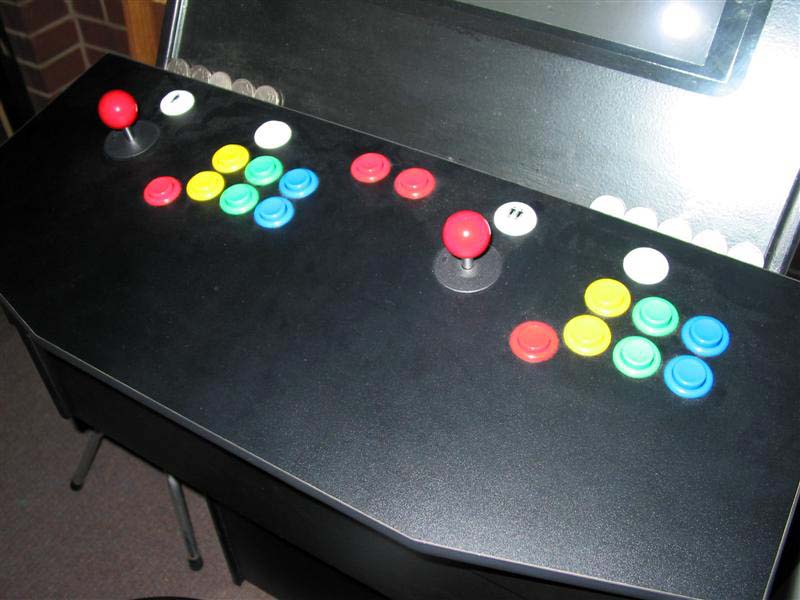
This is my original CP made by Chris from OzStick. Chris did a great job, but I wanted to redo my CP using a LEDWiz device.
I wanted the full RGB treatment, so that means 3 outputs for each button. With 20 buttons it will require 60 outputs from a LEDWiz which means I needed 2 LEDWiz devices to have RGB LED's for each button. One LEDWiz has 32 outputs and you can use multiple LEDWiz devices but just make sure you order them with the appropriate ID's. I got a LEDWiz ID1 and ID2 so they can function together. Incidently you can have up to 16 LEDWiz hardware devices running in tandem not that I would ever imagine someone needing that many.
You may be wondering why you need to replace your buttons to use a LEDWiz. Infact the truth is you don't have to replace your buttons to add LED's to your buttons, but there are two reasons why I replaced mine with Electric Ice Buttons from GroovyGameGear.

Electric Ice Buttons have the advantage that they are translucent and made for running a LED through them. A standard button on the other hand means the LED light coming through is more dull. The reason the Electric Ice buttons arn't clear plastic is because you need to diffuse the RGB output to mix the colours.
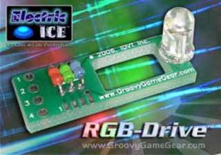
Another advantage of the Electric Ice buttons is they have a special place in the base to insert the RGB Drive Lighting Module and in many ways makes these two devices work together well.
It is an extra expense you will have to weight up and consider with your budget. For me there is no other option since my philosophy is if your going to do it, go hard or go home. And since this hobby is a real passion of mine, it's worth every penny.
I got one of my LEDWiz devices second hand but still in great condition, so many thanks to loadman.
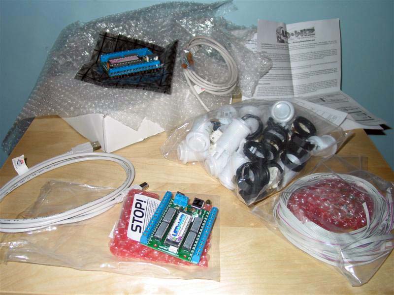
My gear arrived from GGG about two weeks after my order which is not bad from America. Time does go slowly when your waiting for gear for your hobby.
The stuff arrived in good condition, was well packaged so I have no complaints about how it was shipped. This isn't a review of the gear so I'm not going to go into detail about stuff like that.
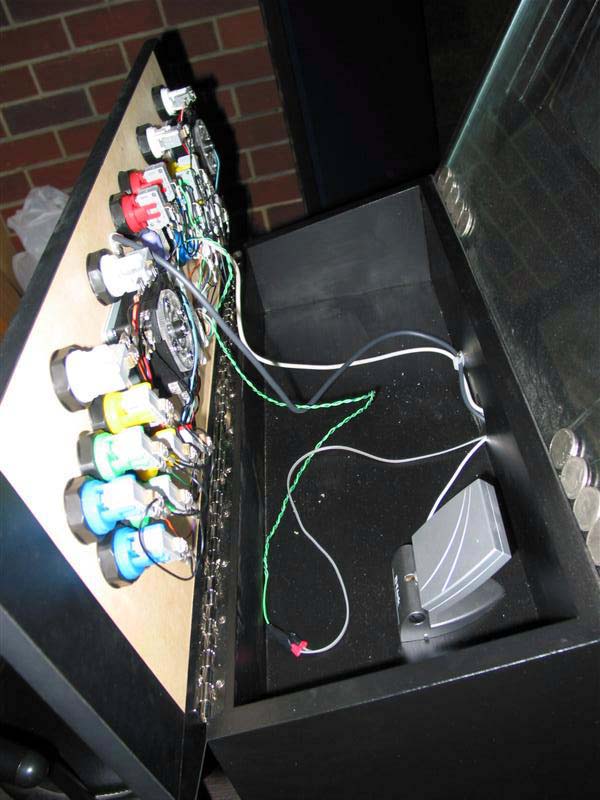
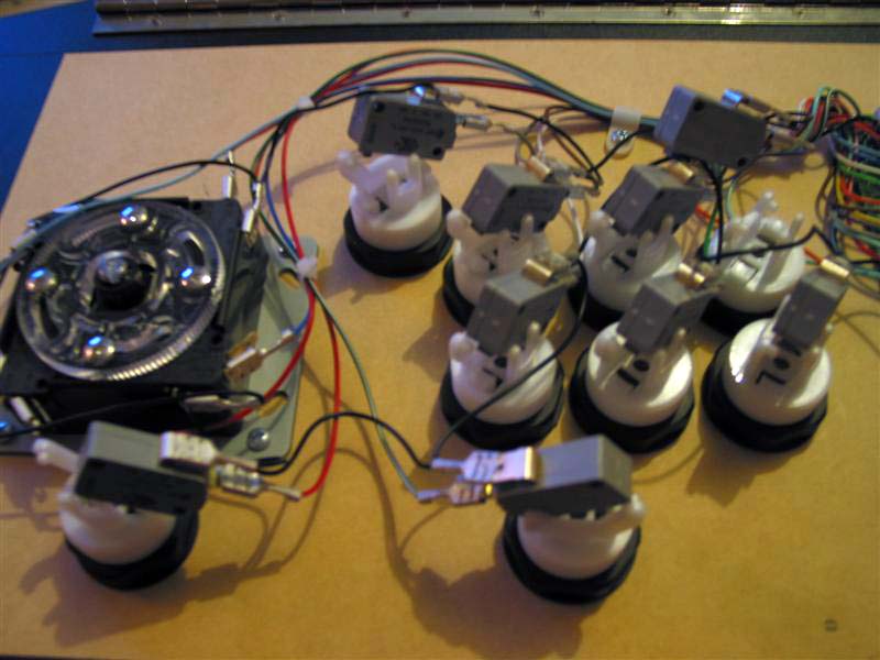
Here is the underside of my CP, and the great wiring job by Chris. The idea of redoing all this wiring was really off putting to me. I'm a coder not an electrician and I hate doing fiddly shit.
So with that idea I made a few decisions; First I decided to keep the original wiring including the micro switches and just replace each button one by one. The main reason for this was when I tried to remove the cramped wires from the micro switches they took a lot of effort to move. In fact I had to get out some pliers to get them apart and nearly jammed the pliers into my CP in the process. I played with the micro switches and the one's from OzStick were Honeywell, and the ones from GGG were from Cherry. The Honeywell switches seemed more "clicky" if that makes any sense. But I didn't mind either of them, so I just decided to keep the Honeywell's already hooked up to my CP for the simple fact it would add whole lot more work swapping them over.

So here I compare the two types of buttons, the one on the left is the GGG Electric Ice Button which is white and taller, and the red one on the right is the shorter one from OzStick. I guess the extra length is for the RGB Drive, but I'm not exactly sure.
Do yourself a favor and get a Push Button Wrench. Using a standard wrench makes life very difficult when adding and removing buttons. With this tool you won't have to unscrew buttons in a certain way so you can access them from the right angle.

Here I begin work swapping over the buttons. Once you get the knack of this it's easy to do even for a cluts like me.
The general process I used was to take out the old buttons one at a time and replace them. Some buttons were hard to unscrew without unscrewing one nearby (because I didn't have a Push Button Wrench), this meant I had to unscrew the whole 7 buttons that are close to each other at once, rather than replace them one at a time.
Inserting the RGB Drive can go either way, but one way is easier than the other and was the side I most commonly used. But for the two admin buttons at the top of the CP I had to put the RGB Drives in the other way so they didn't overhang and get crushed when you closed the CP. That would totally kill the buzz.
While the whole process of taking off the micro switch, unscrewing the button and putting in the new one, pressing in the RGB Drive then putting back the micro switch is easy (even for me) I suggest you buy one extra button and RGB Drive as a spare in case you mess something up. Fortunately I didn't make a mistake and that's saying something. The reason is, these components are made well and they don't easily break.
When you insert the RGB Drive you must press it down firmly until only the small rim around the base of the LED is poking out of the hole in the button. If you don't the button will get stuck and the button will not light correctly. This only means you have to push in the RGB Drive fairly firmly to get it into the hole.
You will probably experience a moment or two when you have to take the RGB Drive out of the button, either from needing to swap sides or you've made a mistake or whatever. The trick is to get a very small screwdriver and just use it's leverage gently on each side of the LED to prop it up. Be very gentle and careful when doing this as not to damage the LED. I found the RGB Drive's to be sturdy enough to take a bit of punishment, but it's best you pry them out as gently as possible.
Inserting the RGB Drive the reverse way in the button is a little more difficult to do, and you need to fiddle with it a bit to get the LED into the hole. My CP is about as small as they come, so in some instances I had to put them in reverse. But thankfully these buttons even have that option which solved the problem for me, otherwise they would have overhung and snapped off. People with bigger CP's will not generally have this problem I would expect.
As you can see I've removed all the main player buttons in one go so the wrench can fit to undo the base of each button. Because this CP was already wired up, I just had the micro switch sit into it's original hole.
I probably don't need a picture for each small step made, but here I have nearly finished the player 2 side of the CP. It's best to get all the buttons in first and just let the micro switch hang in lose only locked in one of the plastic tabs. The reason for this is to insert all the RGB Drives in one go so you don't mess them up and have to take them out again. micro switches are easy to take out and put back in, but I would try to avoid inserting and removing RGB Drives as much as you can.
Try and plan the positions of the RGB Drives as much as you can. Even though they can be inserted either side of the button, one side is easier so only use it if you have to for some reason like from lack of room. Also beware of the connections to the micro switch from getting in the way of the RGB drive when you insert it or vias versa. I had this problem, and had to remove an RGB Drive to put the micro switch of the button below in. Obviously the player buttons are the trickier ones because of their proximity to each other.
Now onto the left side, the same thing basically. I did have a problem where I tightened the buttons on an angle that had the micro switch connectors interfering with the button above them. So be careful of the angle of rotation you have them when you tighten the plastic nut.

Here I have all the RGB Drive's finished. I'm really surprised how easy they were to put in. Especially someone like me who had no experience with wiring up CP's.
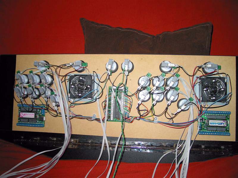
Here the entire CP is done, and the two LEDWiz devices have been screwed on.
Now I'm ready to wire up the RGB Drives to the LEDWiz devices.
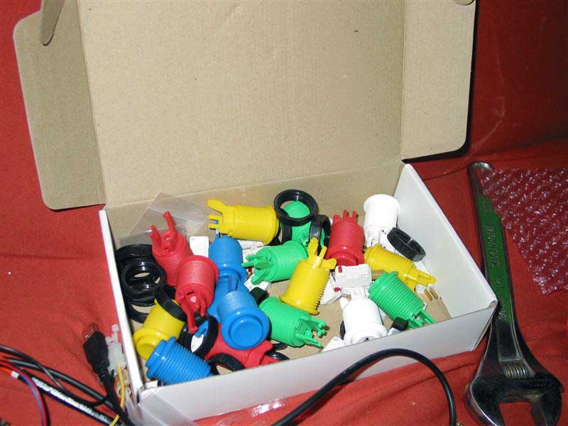
Now I have all these buttons left over, a bit of a shame, but this is for the cabs own good. Having spare micro switches isn't a bad thing either.
A perfect use for two of the buttons, finally I can add some side buttons for Pinball.
I will probably use another one to finally add a power button to my cab.
Part 2: Wiring Up the LEDWiz
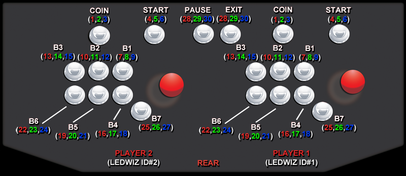
I recommend writing out all the outputs on a diagram of your CP. Make sure you draw your CP from the underside which is the side you are wiring up.
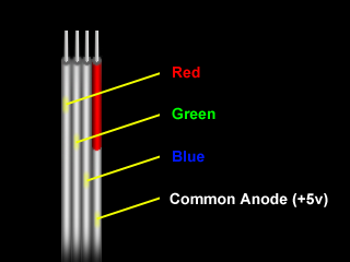
The cables that come attached to the RGB Drives have 4 wires that are marked at the end with a red stripe on one of the wires. If the red strip if facing the right, the order of them is Red, Green, Blue and Common Anode / +5v.
The wires are 28 awg. Randy says a tip for connecting them to the LEDWiz is to strip them about 3/8" long and fold the stripped wire in half before screwing them down.
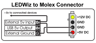
All RGB wires are placed in their own output on the LEDWiz and all of the Common Anode wires need to be stripped back about an inch or more and twisted together. Randy suggested to get 2 lengths of stranded 22awg wire and connect them to each LEDWiz X5 terminal, then use a 20awg wire and connect it to the 5V of the PC power supply. And then to finally use a large "wire nut" to connect all of the loose ends together.
Some suggestions by loadman: "I recommend soldering the wires together (Common Anode) before shoving them in the LEDWiz. You don't want a stray wire to pop out and short out the LEDWiz board. The wire is so thin I found that it would slip out. I also put a 'glob' of solder on the ends of the other wires before I screwed them into the LEDWiz"
You can get maybe 25 monochromatic LED's lit using the LEDWiz from USB, but any more than that and Randy recommends to take power from the PC power supply.
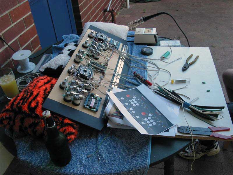
Okay finally time to get setup outside. I called upon the help of a friend of mine to help with the wiring job. Thanks heaps to Credo for all his help. That is his leg on the right of the photo 😛
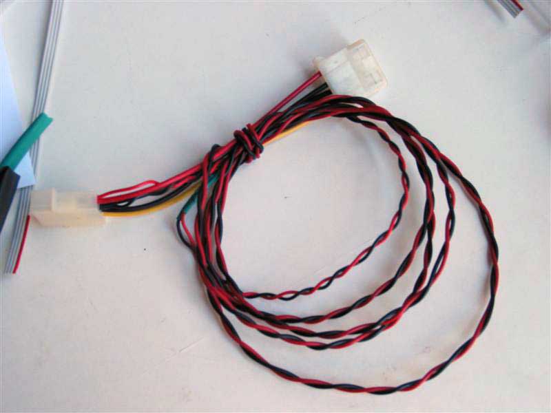
Wiring up a standard PC power cable to some length of wire to power the LEDWiz. It's a very simple item to make. I recommend you use shrink wrap when joining the wires. Shrink wrap creates stronger connections, protects them from shorting and looks nice and neat.
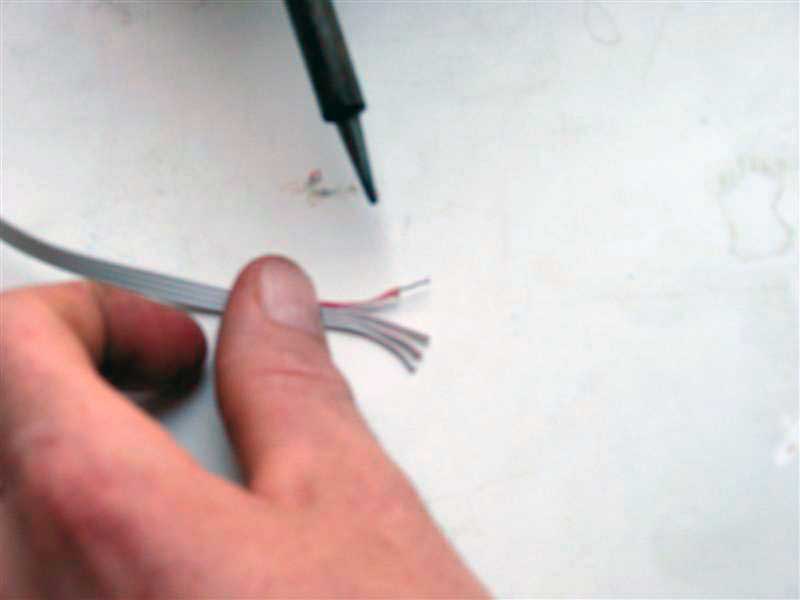
The low gage wire attached to the RGB Drives is so small it's actually quite a task to strip the wire back as the wire cutters we had didn't go that small. But Credo found a nice method for stripping the wires, and that was to use Soldering Iron to burn off the ends by scraping them off with the hot iron.
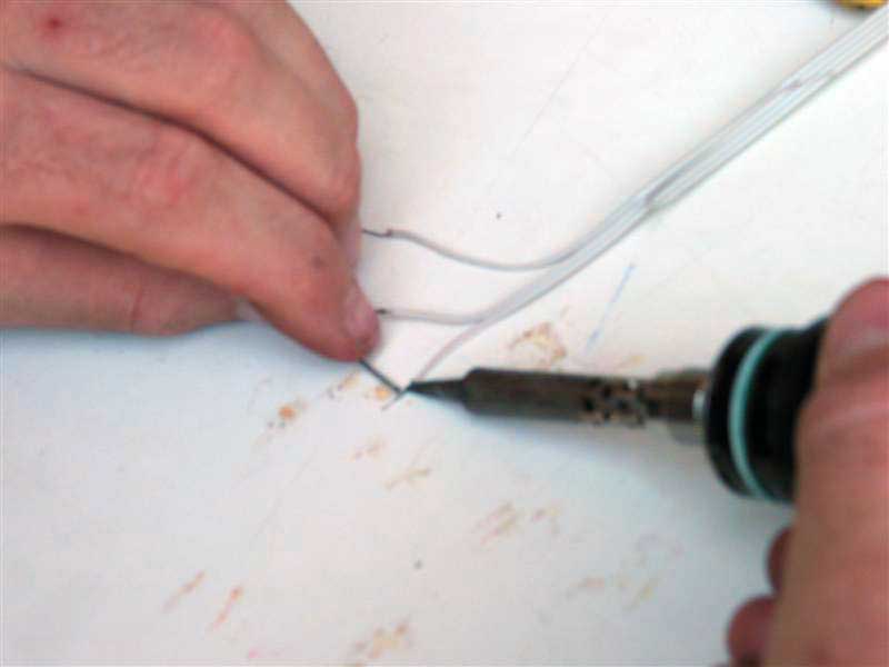
Because the wire is so think it's recommended to add some solder to the ends of the wires. This will mean they are much more secure in screw terminals.
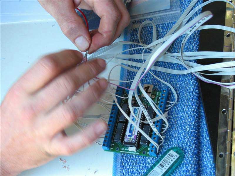
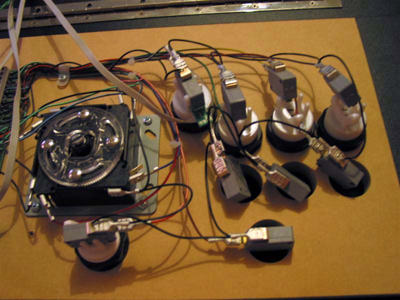
Here the arduous task of wiring each RGB Drive to the LEDWiz begins. It's not too bad I guess with two people it didn't take too long. The soldered wires helped create secure connections. The Common Anode wire is left for now, we'll deal with that later.
Here you can see all the Common Anode wires twisted together, soldered, then shrink wrapped. Again, this method creates a strong and clean looking connection. There is a red wire running off Common Anode to be placed into the X5V terminal.
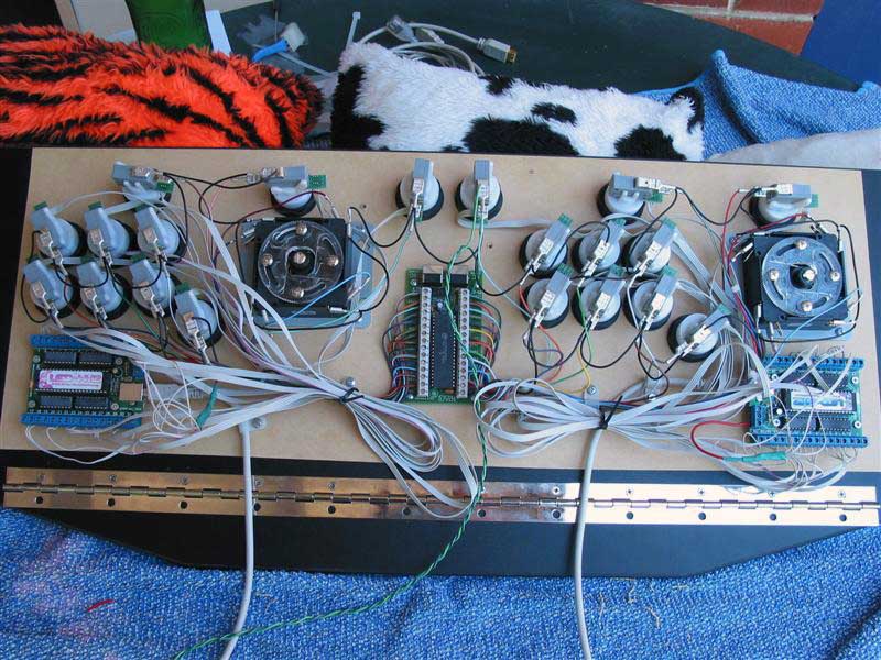
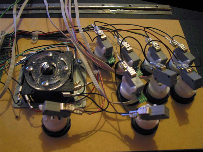
And here the finished result, using cable ties with cable straps to keep them tidy and out of the way. You could decide to shorten the cables for a neater look, but I didn't find it necessary. You will need to mark the Common Anode wire with a Red Permanent marker if you shorten the cables as the red line doesn't always run all the way along the length of the cable.
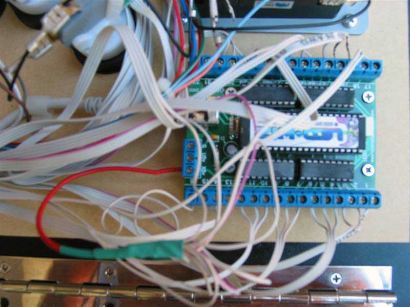
Here we can see a bit clearer the red wire attached to the Common Anode that goes into the X5V screw terminal.
Another point to not is that if you are going in order 1,2,3 - 4,5,6 etc. like I did you will get one that runs across from the top terminals along to the bottom. This is no problem to do, just break the wire enough so it reaches across.
The final step is to get the power cable made earlier and run two sets of wires from Ground and 5V off to each LEDWiz to power them.
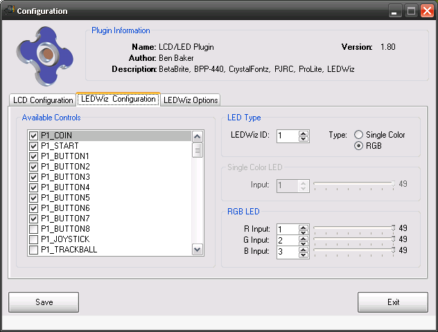
Here I setup the outputs in my LEDWiz Plugin. This is really easy to use as it will light your buttons in realtime as you configure them so you can test each LED as you go.
I was pleased to find that all my RGB buttons were working as expected and setup correctly.
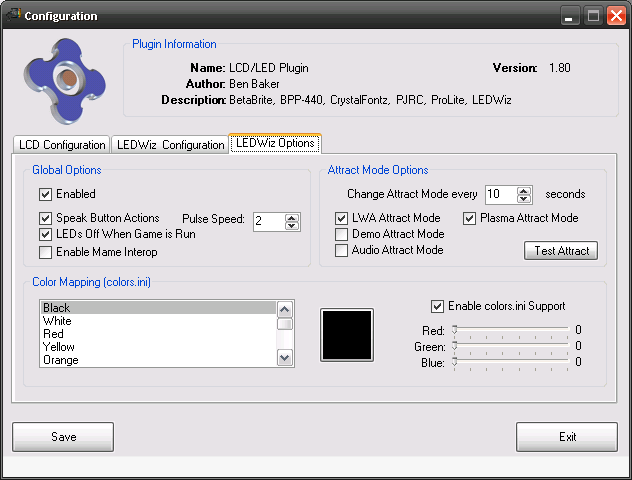
Here I use the Test Attract button to see what the LEDWiz can do. It looks bloody great!
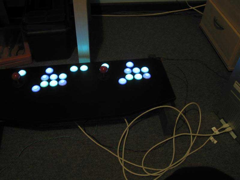
And here is my CP being tested with my Plugin. Everything seems fine.
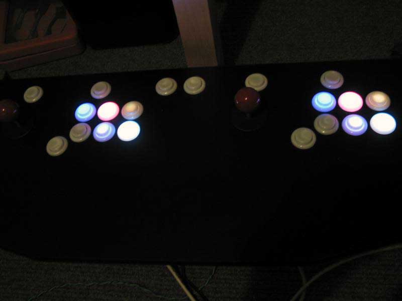
The photo's don't do the LEDWiz any justice, the buttons look great running Attract Mode.
 ]
]
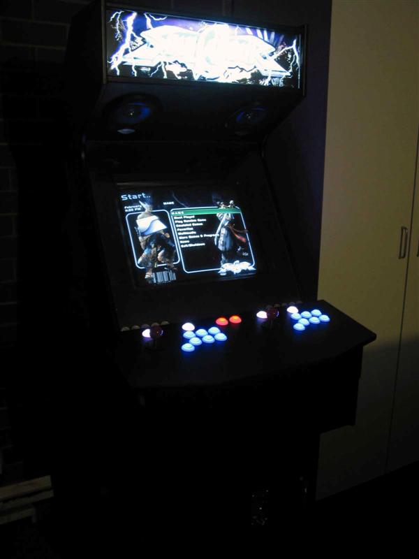
And here is the finished product back on the cab. This has quickly become one of the coolest features of my cab. I'm happy with the product design and considering I have never wired a CP up before it was much easier than I thought. Of course It would have taken at least twice as long to do without the help of Credo. We got the majority of the wiring done in about 3 hours, which is not too bad.

Videos
Here are some videos of the LEDWiz in action.
Video 1 Here you see some basic lighting in GameEx
Video 2 Here there is game specific lighting using colors.ini
Video 3 Here I mess up and select the wrong thing, but then I show the speak button actions feature
Video 4 This shows the attract mode
Video 5 Another attract mode sequence. This one shows some of the plasma attract mode too.
Video 6 Close up of the buttons in action in attract mode.
Video 7 And another video of the attract mode.
Video 8 This shows MameInterop in action flashing the LED's when you insert coins in DigDug.
Video 9 Again this shows MameInterop trigger a LEDWiz event when you press pause in MAME.